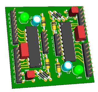
It only took about 12 days to from order to mail man at my door step. I was like a kid at Christmas opening the heavily packing taped package from China. After I gnawed, sawed, ripped and cut the package opened, I ran to the garage, scored the board with a box knife, snapped a couple in half and started soldering. Wow, was I excited to get going! 30 minutes later, I had 4 PICyStiX in hand and was off to my eagerly awaiting bread board. My only issue was that I was out of the correct size of momentary switches. Luckily, I had a handful that would fit, if ever so snugly.
<insert failing warp drive sound> Oh no! I forgot to pour the ground plane before I sent off the board. Back to the garage to start soldering in 7 jumper wires (it could have been worse).
Engines online! After an hour of tedious soldering, my four PICyStiX were ready to be retested. This time they worked.
I have since populated, fixed and tested 8 boards.
- 2 PIC16C84
- 2 PIC16F628
- 2 PIC16F54
- 2 PIC16F88
I have already started on version 2.0 that will bring all 16 IO pins to headers (Vcc and Vss too). If you are interested in the schematic and gerber files, just post a note below.


Thanks for this article, I'm very interesting about pic micro controller.
ReplyDeleteI hope this help me too.
This comment has been removed by the author.
ReplyDeleteThis comment has been removed by the author.
ReplyDelete