Sunday, October 28, 2012

Getting Started with AVR

About a year ago, I placed an order for a few extra PICs and at the same time ordered a couple ATMEGA328-PU micros at the same time.  I had only started to read about the AVR and this one looked like the perfect starting point. At that time, in the past, all of the Arduino boards were way too pricey for my cheap skate PIC background, but the simplicity of creating an AVR programmer drew me in.  

Now, it is worth saying that the two ATMEGAs that I purchased would have gone unused for a long time, possibly forever, if not for a bit of luck.  I had placed an order for some PCBs at ITEAD Studio and selected the "*Open Source And Get 2 More Additional Boards" option.  One of the extra boards they sent me was my own and the other was a Uno clone from JMN Electronics
In true good form, Joan placed her email address on the silkscreen.  Using that, I was able to contact her and get a BOM (had I a bit more experience with the Uno, I could have figured it out).  Since, the Uno uses such common parts, I had everything laying around to populate the board (including my aging inventory of 328's).

Now starts my frustration.  Of course I had the AVRs and a board, but I did not have a way to program the boot loader on them.  If you are like me, you are not too aware of your options and it is time to get Ghetto.  Thanks to Google and AVRProgrammer.com, I was able to whip together a FrankenProg (combine with AVRdude and you have something workable).  Yes, that giant hunk of glue is my concept of a strain relief and I have no intention of showing the nightmare that is the underside of the proto board.  I have to say that it worked perfectly and I was able to complete my clone Uno, but I am really dissatisfied with something like the above.  Maybe 10 years ago it was fine, but there is no support for OS's after XP and certainly not X64.  When I was reasearching programmers, I also came across the USBASP and it turns out they can be purchased on Ebay for less than $5.

As excessive reading would have it, I found that the USBasp by Lcsoft was upgradeable and works with Windows 8 x64. Ding!
The reasons I like this particular one are:
  • Inexpensive not cheap
  • Firmware is upgradeable via placing a second USBasp back to back and shorting JP2 on the unit to be upgraded
  • Two of them are $7 shipped to your door
  • JP3 is still available for slow programming (when you brick your chip)
  • 3.3V and 5V supply voltages
  • It is USB and is supported by AVRdude
  • The Arduino software can use it to burn a bootloader


In short, don't waste your time trying to build a programmer.  If you are coming from the PIC world, we could always build something cheaper than we could buy it (thank you high voltage programming).

Sunday, October 21, 2012

Sending Data Over Wireless Modules

Five years ago, sending data back from remote systems has always been a pain and required a good bit of engineering knowledge.  Fortunately, we can buy a set of wireless transmitter and receiver modules for $2.  A few details about these modules:


  • They operate at 433MHz
  • Data rates (baud) should be kept to 4800bps or lower (quality starts to diminish above 4000bps)
  • The transmitter can be powered with up to 12V, for greater range
  • Range is greatly increased by adding a 17cm antenna (straight piece of wire) to each module
  • The receiver will pickup a LOT of noise, so expect good and LOTS of bad data
  • Debugging data from the receiver is greatly simplified with a basic logic analyzer for $12
  • The receiver relies on the transmitter sending a preamble burst of data, so that it can lock onto the strong signal (vs background noise).  I recommend sending about 30 characters of 0xF0 before sending real data
  • Best practice is to utilize Manchester encoding for the data (I did not)
  • IT WILL BE NOISY. Be prepared to write code sift and sort out noise from data
  • ATAD == data input.  For the life of me, I cannot find out what this stand for.
A quick tip for starting out is to not even worry about the, "Odd" baud rate of 4000 and just start out with a standard UART rate of 4800bps.  One reason is that for debugging purposes, you can tap the RX port of a USB->TTL adapter to the ATAD pin and monitor the data going over the air.


Tuesday, October 2, 2012

Serial Communication with Bluetooth Module

With my temperature sensors working, the next step is to start getting data back to the PC/Mac/RPI (Raspberry PI).  Right now, data can be sent back via to ways:
  • RS232 via a standard USB serial port (and the supporting max232 circuit)
  • RS232 over Bluetooth
I reached one of the milestones in programming where I really needed to see real time debugging information.  The first step was to wire up a standard serial port and start dumping data to Putty (o'l standby).  Interestingly enough, on one of my shopping sprees I ran across a $9 Bluetooth serial module and I could not be happier.  I have scrapped my legacy MAX232 -> USB in favor of a Bluetooth module that accepts 3V-5V input (FYI, I think it outputs 3V signals).  It could not have been simpler to plug in the module, run GND, 5V and a line from the PIC.  A few minutes later, it is discovered on the PC and the serial port is added as COM6.  Nice.  Now that is one less cable between the PC and bread board.


The tricky part is that these devices default to 9600 8N1.  In reality, this is a very reasonable number for most applications.  However, I needed to drop it down to 4800bps due to the clock speed I am running.  The trick to that is that the BTM can only be configured via the terminal when the BT link is not active.  To do that requires connecting the BTM to the host via a TTL serial adapter.

Once communication is established, one item to watch out for is the firmware.  Some adapters come with HC06 (Linvor 1.5) and others come with HC05.  While, HC05 has more configuration options, I am not sure too many of them are useful.  To really dig into it, visit Byron's Blog.
Fortunately, there is a lot of information out there on configuring this BTM.  A quick Google for, "Bluetooth and linvor" will turn up a wealth of resources for customizing the BTM or you can download the manual.

Quick Start Guide:
  • Set Baud Rate - Sets the baud rate. Baud rate is set by an hexadecimal index from '1' to 'C'
    • Indexes are: 1:1200, 2:2400, 3:4800, 4:9600, 5:19200, 6:38400, 7:57600, 8:115200, 9:230400, A:460800, B:921600, C:1382400
    • Send: AT+BAUD<index>
    • Response: OK<baud rate>
  • Set Bluetooth Device Name - Sets Bluetooth Device Name
    • Send: AT+NAME<device name>
    • Response: OK<device name>
  • Set Bluetooth PIN Code - Sets the security code needed to connect to the device
    • Send: AT+PIN<4 digit code>
    • Response: OK<4 digit code>
  • Check Firmware Revision -Get The Firmware Revision Number
    • Send: AT+VERSION
    • Response: Linvor1.5


Monday, April 23, 2012

Why the AVR is better than the PIC

It has only been a few short weeks since I took the plunge back into microcontroller programming and already I have regrets.  Back in earlier posts, I listed a few reasons that I am sticking with the PIC.  Since then, I have solidified my position even more by purchasing a PICkit2, and installed the CCS and Microchip C compilers.  Sadly, my frustration continues and it has absolutely NOTHING to do with the chips and everything to do with the development environment.

20 years ago, the devices were so small (RAM/ROM/Flash) and there were so few variants that developing in assembly was not too bad.  With the variations of chips today, it would be foolish to write almost anything for these microcontrollers in assembly.  If you are old enough, or hard core enough, you know that writing reusable and modular (library) code in assembly is akin to stabbing a pencil in your own eye (it hurts).  A simple example would be to imagine upgrading code on a PIC that had a single W register to a PIC with 4 W registers.  Sure you could just migrate the code, but all that optimization that could be leveraged is lost!  Hence, we have C.

I will be the first to admit from a hardware size, what I have at hand is pretty nice.  I have a handful of powerful and flexible PICs at my disposal.  However, the compilers are really starting to wear me down.
  • The free compiler (from Hi-Tech) is almost worthless when the optimization expires
  • The available C compilers are between $150 and $500
  • Don't forget about maintenance
  • Due to copy write restraints, I cannot share with my readers how I customized the code to fit a particular situation
  • If the reader does not have the compiler, my source code is all but worthless
  • You help $timulate the economy by buying a new compiler for each chip family (16 vs 18 vs 24).
So, in short, here I sit trying to squeeze coding into a tiny device and all I can do is produce bloated code files.  And let me assure you, there is a difference.  My once simple temperature with RS232 will no longer fit onto the device.  Previously, it was only filling up 70% of the code space.

Of course hindsight is 20/20.  Right now, as I look over my shoulder I wish I would have dropped $50 on the AVR Dragon instead of the PICkit2 (mind you, the PICkit2 really is a fantastic setup).  So, I implore you to not follow my path and shift (or start) with the AVR as soon as possible.  And, I hate to say it.  I don't think you (or I) will look back and think we made the wrong decision.  Look at some of the benefits:
  • tried, true and free compiler with GCC
  • -O 3 (gcc's optimization flag)
  • The $ that would be spent on the compiler can go towards a logic analyzer, Oscope or a bench power supply
  • Ability to switch among device types w/o buying a new compiler for each
  • Ever growing list of user created libraries that you can freely copy, change, enhance, and share
    • 1-wire
    • I2C
    • USB
    • Manchester encoding
    • RS232
    • Wireless modules
    • List is long and keeps growing
  • AVRfreaks as a resource (yes, they are a wee bit hostile towards PIC people)
  • Hobbyist and Magazine support is bar none
  • Let's not forget the quick and simple Arduino
  • I consider all the other items (price, features, pin count, availability) to be the same
Am I switching?  Not right now.  But be assured when I run out of my supply of PIC's, the inventory and tools will be refreshed with AVR's.
Am I wrong or am I missing something obvious?  Post below and let me know.

Sunday, April 22, 2012

Starting out with the DS18S20 Digital Thermometer

When I first started this project, the DS18S20 thermometer started out as a real winner.  Looking at some of its key features, how could it get much better?
  • Communicates over a simple 1-wire interface.  No waste of I/O ports
  • Multi-drop and individual addressing allows more than one device to share the same I/O pin
  • Cheap (my weak spot)
  •   ±0.5°C resolution
  • Digital communications means the devices can sit at the end of a long bus run w/o loss of accuracy
Look at how simple this device is to hook up to the circuit.

All that is needed is a standard 4.7KOhm resistor.  It only took about 5 minutes (thanks to the included libraries from the compiler) to start talking to the device.  In about 30 minutes, I was able to put together a simple program that would continuously read the temperature and send the data over RS232 to my PC.  The next step was to add a few sensors to the bus and see about addressing them individually.  <crash>  Turns out that my frugal nature of using a 15+ year old part bit me.  Each device is addressed via a 48bit number.  While keeping track of 1 or 2 of these nifty devices would not be a problem, any more than that and the C84 is out of RAM.  In all fairness, just about any reasonable microcontroller is going to quickly run out of RAM keeping a track at 6 bytes per device.  Secondly, I discovered that the firmware required to discover all the devices on the bus is not that small either.  By the time I extended the code to enumerate the bus, I used up almost 100% of my 1K of my EEPROM.  Fortunately, there are still an abundance of I/O pins on the device that have not been used.  So, for my design I am going to limit the number of DS18S20's to 5 (RA0-RA4).  If I really need to expand the number of temperature sensors, a simple solution of a MUX (151) and an analog switch (4066) would be where I would turn.  Using pins RA0-RA3 tied to a 74HC151, and the mux's outputs tied to 2 74HC4066's RA5 can be used for all the DQ lines (perfect since it needs a pullup anyway).  With that in place on the breadboard, the PIC can now easily address 8 thermometers w/o any complicated 1-wire coding.

The down side is that the project cost has just gone up by $2 as has the complexity of the board.  If I were going at this greenfield, I would be much better served putting the extra $2 into the PIC device I was going to use.  A $4 PIC would provide a few hundred bytes of RAM and about 8K of FLASH.  With a device that size, the issue of the firmware size and 6 byte device address storage would be removed and and there  would be no need for external components.  Oh well, glad I keep a drawer full of shoe horns.


Monday, April 16, 2012

PICyStiX

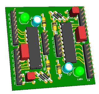
One of the first things I HATE about bread boarding is the setup nightmare.  How many times must I wire up a power LED, reset circuit, ISCP, xtal, and it goes on and on.  My first task is to design a PIC carrier similar to what this individual did.  Thanks to China, we all now have inexpensive board manufacturing at our disposal and I am about to take full advantage of it.  My only constraint is that I am cheap (really, ask my wife).   Iteadstudio will make 10 5cm X 5cm  PCB's for $10.  Who can beat that!  With a little mind optimization, I was able to design a PIC carrier card in 2.5cm X 5cm.  Great!  Now I can cut the PCB in half and get twice the number of PICyStiX.
3D PIC16F carrier board

It only took about 12 days to from order to mail man at my door step.  I was like a kid at Christmas opening the heavily packing taped package from China.  After I gnawed, sawed, ripped and cut the package opened, I ran to the garage, scored the board with a box knife, snapped a couple in half and started soldering.  Wow, was I excited to get going!  30 minutes later, I had 4 PICyStiX in hand and was off to my eagerly awaiting bread board. My only issue was that I was out of the correct size of momentary switches.  Luckily, I had a handful that would fit, if ever so snugly.

PIC carrier board

<insert failing warp drive sound> Oh no!  I forgot to pour the ground plane before I sent off the board.  Back to the garage to start soldering in 7 jumper wires (it could have been worse).

Engines online!  After an hour of tedious soldering, my four PICyStiX were ready to be retested.  This time they worked.

I have since populated, fixed and tested 8 boards.
  • 2 PIC16C84
  • 2 PIC16F628
  • 2 PIC16F54
  • 2 PIC16F88
In the end, the worst thing I discovered is that the new PIC16F parts actually have three additional I/O pins (RA5,RA6, and RA7), that I did not run to the headers.  On the better side of the coin, I have some very handy modules to use and a couple fantastic lessons learned.

I have already started on version 2.0 that will bring all 16 IO pins to headers (Vcc and Vss too).  If you are interested in the schematic and gerber files, just post a note below.

Sunday, April 15, 2012

Requirements

Before I get too far down the road, I need to establish some high level specs.
The end product will:
  • measure incoming water temperature (EWT)
  • measure outgoing water temperature (OWT)
  • measure return air temperature
  • measure supply air temperature
  • measure supply humidity
  • measure outside temperature
  • log the data somewhere somehow
  • display the data on an LCD (of course)
It will be nice to have:
  • measure KWh usage for whole house 
  • measure KWh usage for HVAC
  • pulse monitor for water meter (have one sitting in the closet)
  • keep track of seconds the burner in the water heater is running
  • RTC for data tagging
Devices:
  • DS18S20 temperature sensor (few in the drawer)
  • PIC16C84 (if we cannot smash the code in there, we will buy a bigger one)
  • HSU-07 humidity sensor
  • 16x20 LCD (need a good cheap source)
  • Bluetooth serial module (these ain't the dark times with cables and stuff)
  • 433MHz wireless modules (just in case)
  • 74HC138 will slim down the 1-wire
  • Flame sensor - Cool!
Misc:
  • Google for data logging
  • DesignSpark for PCB creation (seriously, I tried Eagle and could not figure it out).

Going Geothermal

In December of 2010, I finally made the decision to replace my aging HVAC and update it to a vertical closed loop geothermal system (Yes, it was expensive.  But, it was the right thing today and I wish more people would made decisions based on the future and not the hear and now).  While researching geothermal, I ran across individuals using Web Energy Logger to monitor their home ecosystems. For the longest time, I watched this house up in Plano and was been envious of not only the monstrous floor plan, but of the kick ass WEL monitoring system that is installed.  This simple event rekindled my interest in the PIC microcontroller and dusting off my BSEE (paper only).

Back in the mid 90's, while I was working at a small engineering company in Austin, TX, I spent an entire summer designing small control modules with the legendary PIC16C54 and PIC16C71.  Wow!  Things sure have changed.  Back then there were few alternatives (enjoyable) to PICs and they were quite the fan fair.  Today, the playing field is a tight battle among Microchip PIC, Atmel AVR and the TI MSP430 series of microprocessors.  With my rediscovered interest in microcontrollers (and being off the scene for so long, I figured I would dabble in each of them a bit).  Rather than bother with that story, let's just say old habits die hard (you always retreat to what you know).

If you are interested (if not skip on), this basically sums up my decision to stick with the PIC.
  • I already know PIC assembly (but that ain't hard and I have no intention of using it)
  • Free C compilers are available for all of them
  • I don't use a Mac or Linux, so those are not driving factors
  • The prices are about the same
  • The MSP430 is too modern at 3.3V
  • I already had a PIC programmer and two PIC16C84s laying around (yea, I typed 'C')
In all honesty, if I were to start all over, I would have picked the AVR, just for the social popularity.  But, here we are and here we go.